The road to nirvana |
|
My journey into Photography, Horology, and Audiophilia |

5V boost power supply
Lately I've been thinking how I would power my soon to be assembled Gamma 1 DAC. It is powered from a USB, or from a really clean 5V DC power source, not those found at Ace hardware, or similar.
A bit of frustration...
I can actually just use a 9V battery with a 7805 regulator and I'm done. However, I have to charge the 9V when it gets exhausted, and I don't have such charger and not willing to invest on one.
The bigger issue, as per my experience, is that most 9V batteries locally available are the 175mAh type (I'm using an Energizer 175mAh rechargeable). So if my AMB Labs Mini3 is idling (read: not playing music) at 26mA, then I barely have 7 hours of idling time. But what happens when it plays music? Darn! I could have asked somebody to buy me a CTA 325mAh in the US which I did, but she didn't find any as she's on her way back from NY.
So what is more appropriate? The γ1 DAC is so small with all the USB, COAX, Optical inputs all the size of a credit card. I wanted to have a small power supply to boot and hate those ugly wall warts that spit out more voltage than what's in the labels.
Going AA or AAA...
Since I already have a GP charger, and have invested on AA batteries for my speedlights, I decided that the batteries either be AA or AAA. To get a working voltage for a USB device, I need 4 of which giving 4.8V. Done, isn't it?
But I don't want to bring 8 batteries! (4 as spares) So if I can cut the number by half, then it works better for me. But 2 x 1.2 is only 2.4V so how can I make 5V from it?
Needing a boost
I've never ventured with such power supplies yet so I needed to do a look at chip manufacturers such as Linear Technologies which I've ordered from in the past. But this time I'd like to try Maxim. Not the magazine, ok!
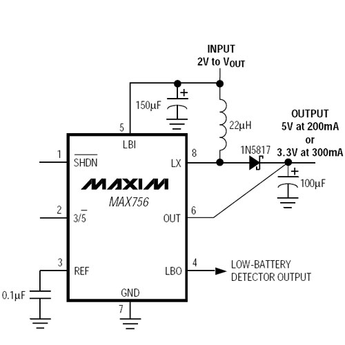
From the available datasheets, there's a chip with really simple application note - the MAX756... All I need to add are a few parts and I'm done.
Here's the application note schematic from Maxim

Sourcing the parts
While the MAX756 chip is available from Farnell, the recommended 22µH inductor is not. While there are other inductors, they don't meet the design requirements- 1A and 0.030Ω DC resistance.
This prompted me to request a sample from Coilcraft, manufacturer of the recommended inductor. The part number is PCH-27-223. Should this sample don't make it, I'll make do with the MURATA POWER SOLUTIONS 22R223C, order # 1077051 from Farnell. It has a higher DC resistance of 0.09Ω which may cause the efficiency of the MAX756 to be less.
For the capacitors, it is recommended that low-ESR types are used. This include Sanyo OS-CON, Nichicon PL series, or United Chemi-Con LXF series.
Until such time that I get the inductors, I can't start making it nor make a PCB for it.