The road to nirvana |
|
My journey into Photography, Horology, and Audiophilia |
Working with Supports in UP Studio 3
January 9, 2023
Supports, the necessary evil. An FDM 3D printer can't lay anything on top of nothing so that's where supports comes in. They are temporary structures to provide support (sic) for the actual layer needed by the model. Well, sometimes we can get away with if the 3D printer is good at bridging but that won't be appropriate for all models.
In UP Studio 3 just like the version 2, there is an excellent Supports Editor. Here are the steps in working with supports and how the diffent modes (Basic/Advanced/Expert) affects the visibility of the parameters.
Basic mode
All the basic parameters are available in Basic mode, the tabs are disabled. This is the simplest way of customizing the parameters.
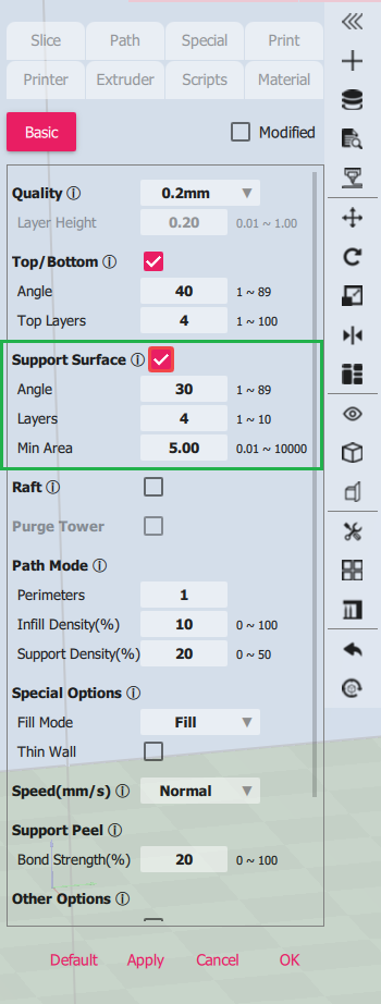
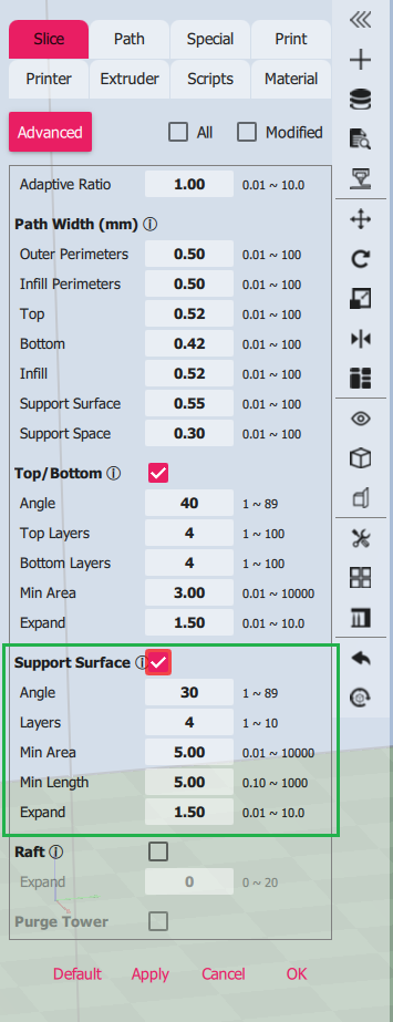
| Support Surface | Enable it using the checkbox for support material to be added to the model. |
| Angle | The threshold for determining support requirements. The smaller the number the less support will be generated |
| Layers | The number of support top layer between model layer and support structure |
| Min Area | Threshold for overhang surface |
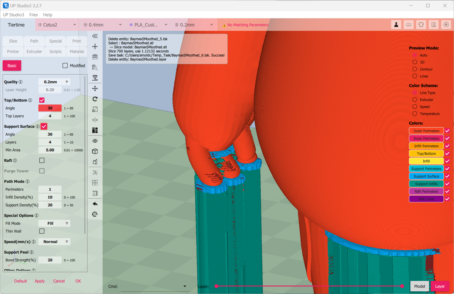
Support Angle value is 30 which covers all fingers of the model. This will print properly, no printing on air.
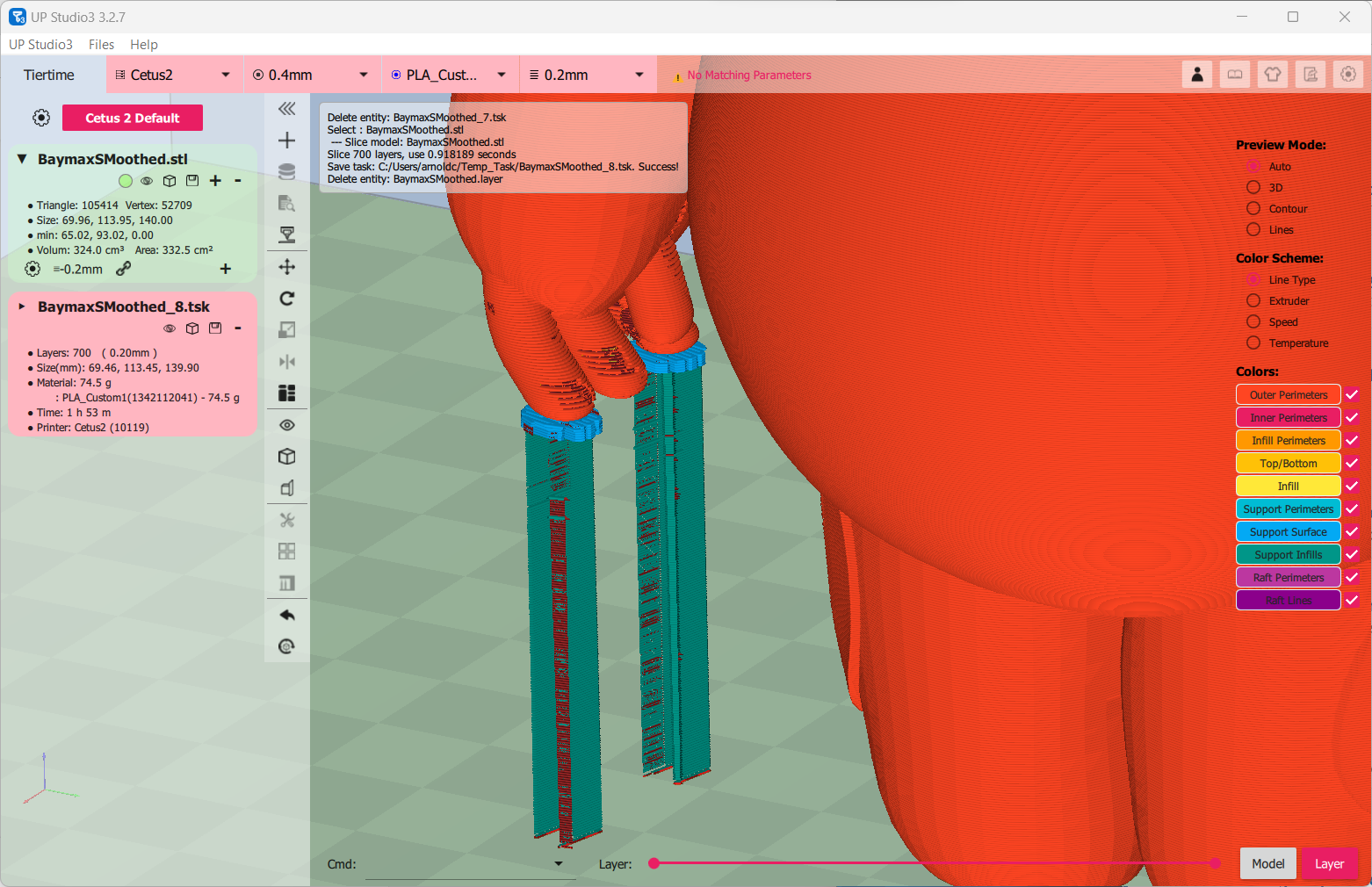
When I changed the value to 20 (less support) we now see the middle finger will be printing on air and that's a print failure.
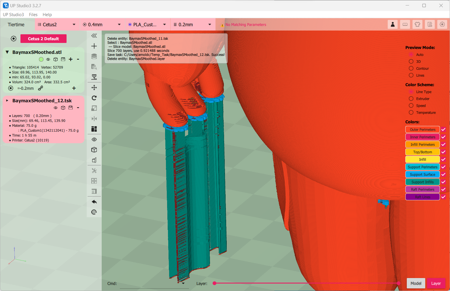
While it seems Angle of 30 will cover the model's support requirements, I see there are unnecessary supports on the finger joints and I'd like to remove them. I could go to the Support Editor or set the Min Area. Here's how supports look like with Min Area = 1 and Angle = 10. Better?
Advanced mode
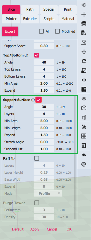
In advanced mode, there are two more parameters that are now exposed.
| Minimum length | Threshold for overhand edge |
| Expand | Expand distance for support regions |
Expert mode
In expert mode, two more parameter are available.
| Stretch angle | Not implemented, hence set to 0. |
| Suspend lift | Used with pointed or edge facing down and determines the number of layers the support will wrap around it |
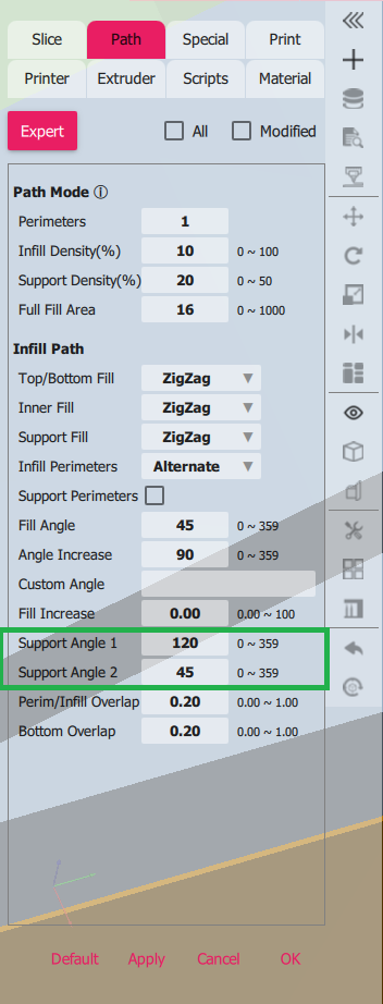
In the Path tab, there are two interesting parameters affecting support. They are Support Angle 1 (default value 105°) and Support Angle 2 (default value 15°).
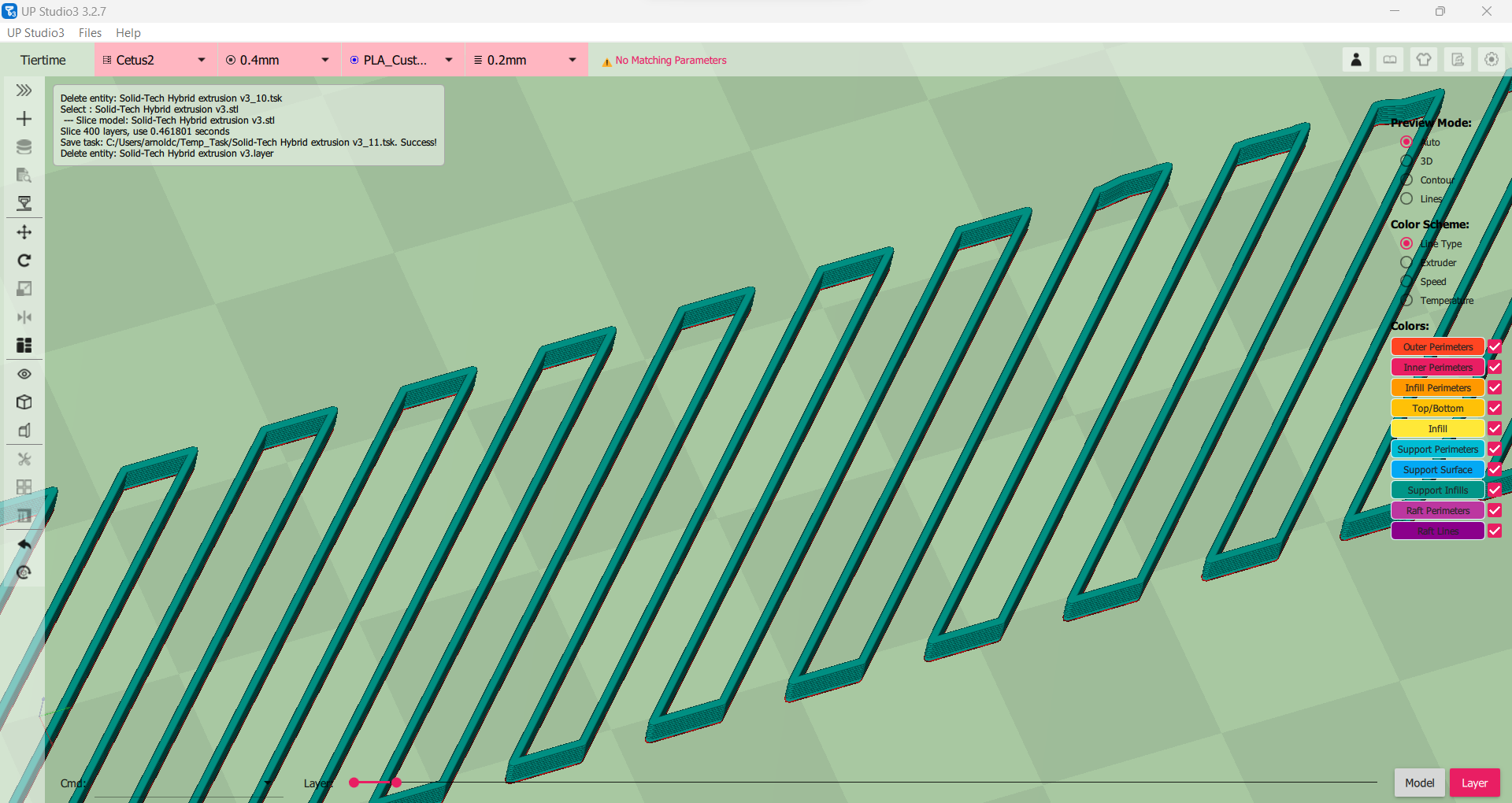
Support Angle 1 affects upper level of the support infill, you can see them as blue in the photo below modified to 120°. The Support Angle 2 value is 15°.
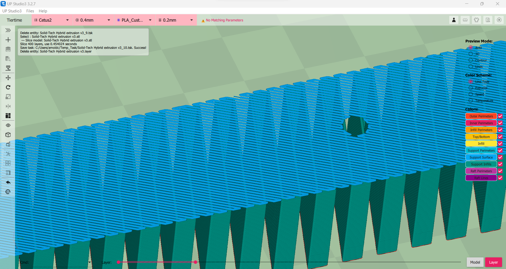
(Support Angle set to 120°, instead of the default 105°)
In the following photo, I changed Support Angle 2 value from 15° to 40°
 I
I
(Support Angle 2 changed to 40°)
Using the Supports Editor
In order to invoke the Supports Editor, click the
 Design
Support for Model button on the vertical Toolbox. In the following
photo, the parameters area has been collapsed to get more real
estate in the model area.
Design
Support for Model button on the vertical Toolbox. In the following
photo, the parameters area has been collapsed to get more real
estate in the model area.
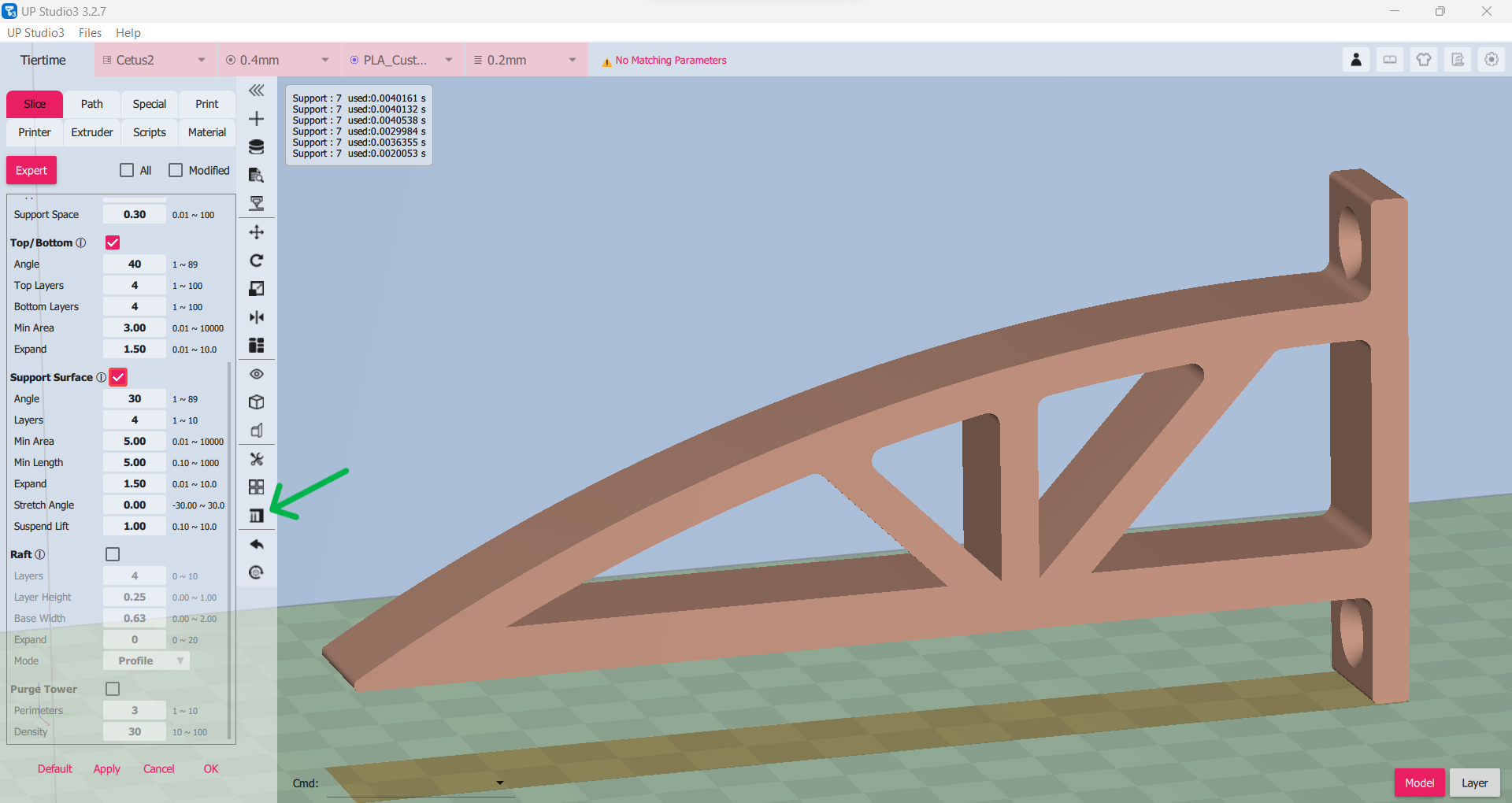
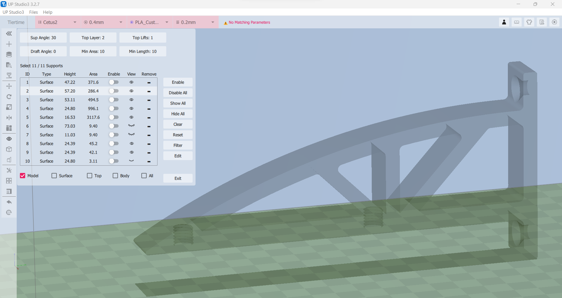
I start working with the editor by checking the Model checkbox and unchecking the rest. I also click the button Disable All to give me a clear view of only the model.
The following photos will reveal different parts of the support as you check the visibility options Surface, Top, and Body. All does not work.
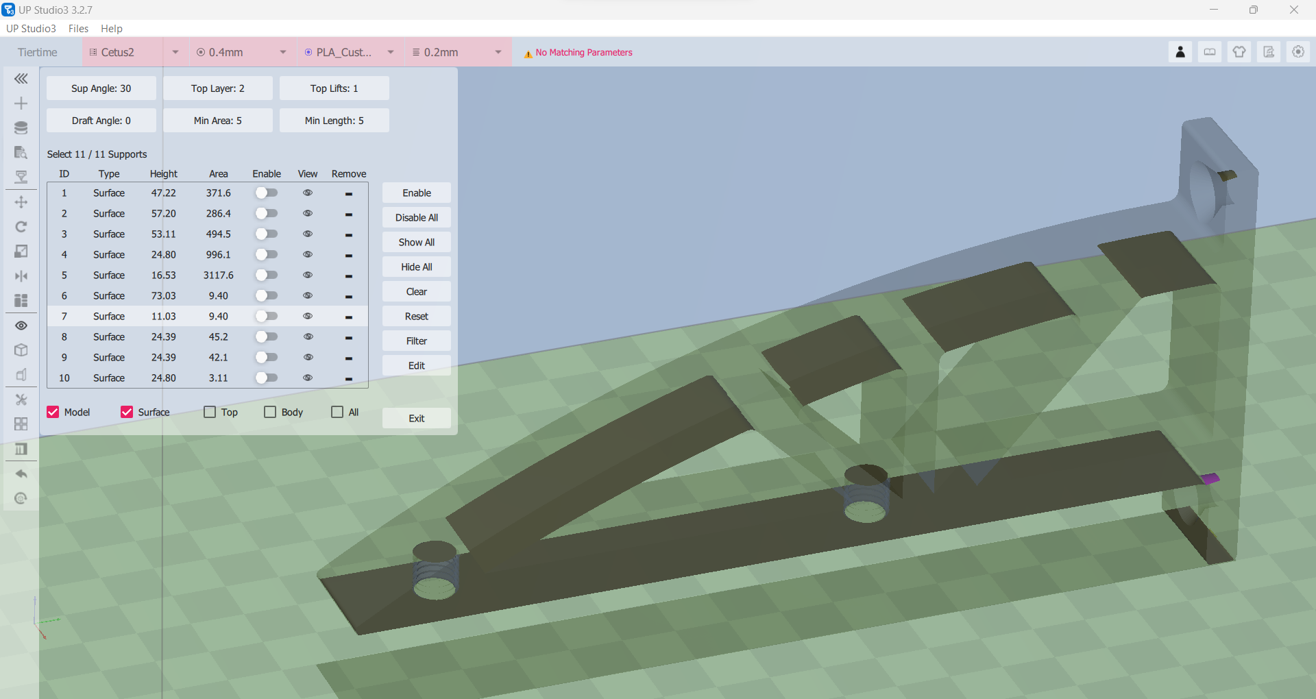
(Model + Surface)
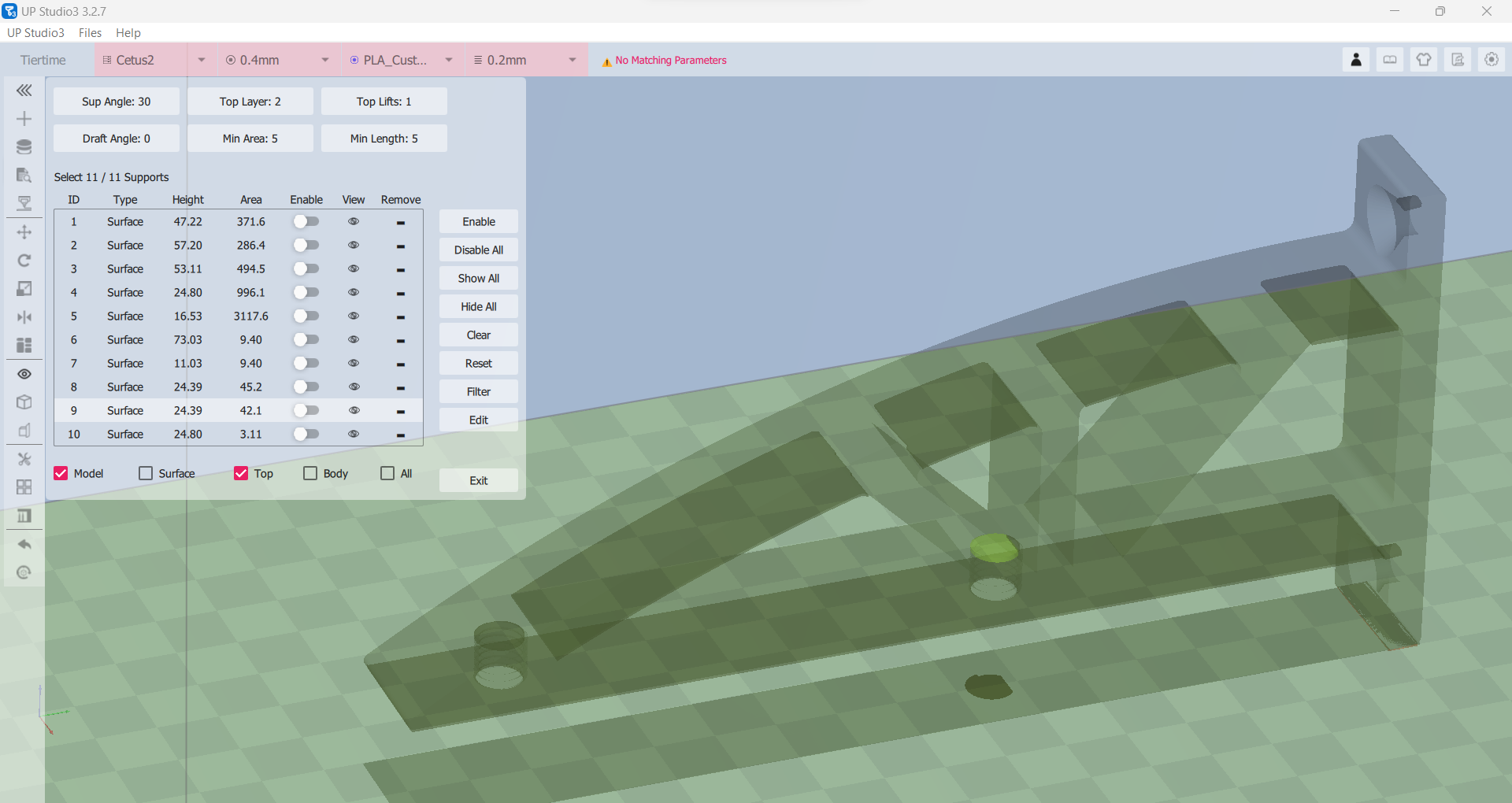
(Model + Top)
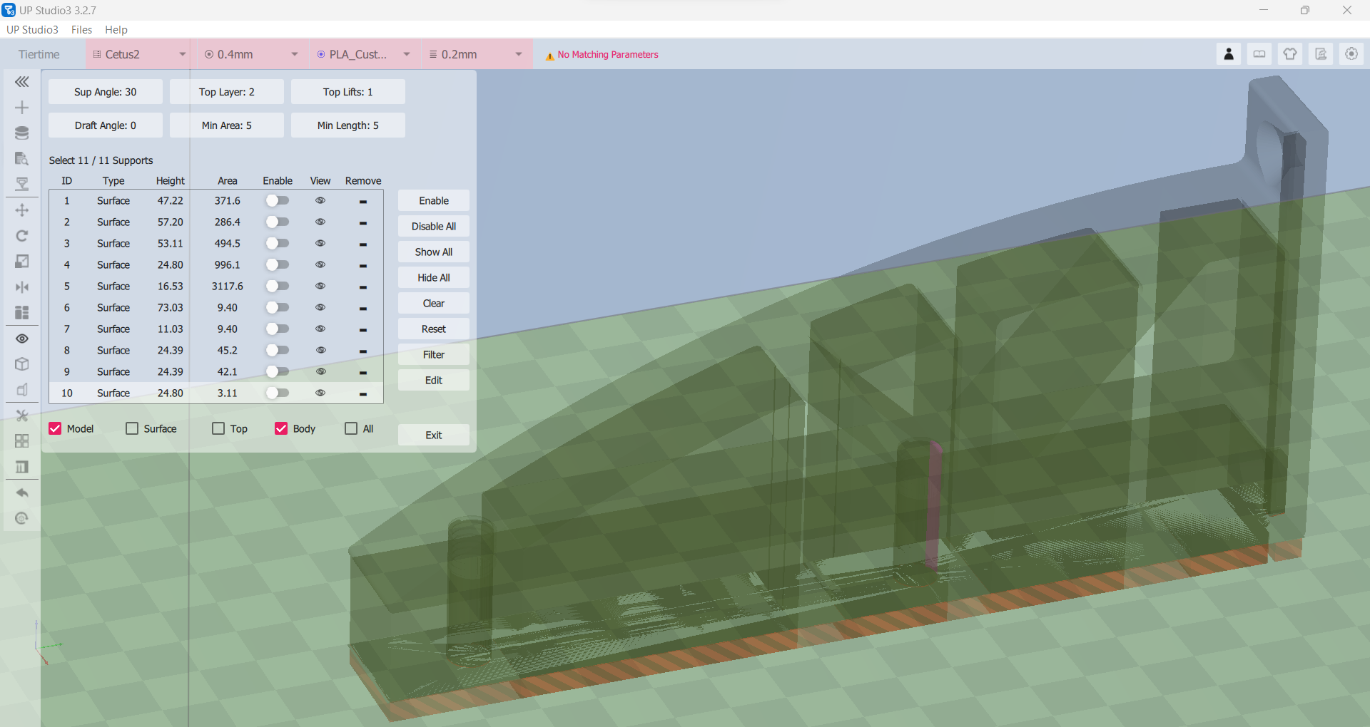
(Model + Body)
Support Editor parameters
The parameters in the Support Editor inherits those you set in the parameters area in the Basic, Advanced, and Expert modes. But once you change the values in the Support Editor, they become the active ones.
| Sup Angle | defaults to the Angle parameter |
| Top Layer | defaults to the Layers parameter |
| Top Lifts | defaults to the Suspend Lift parameter |
| Draft Angle | |
| Min Area | defaults to the Min Area parameter |
| Min Length | defaults to the Minimum Length parameter |
made a PCB using the photo resist method so it will have a nice, professional look. I used Express PCB to do my layout and it's really small, just 1.5" x 2" in size. This is how it looked like with all the parts stuffed onto the board. It has undergone testing and I like what I heard.
Here it is, fully assembled and tested, and looking good. To keep the cost further down, I used cheap RCA jacks. The ground lug is to the left of the RCA jacks.
I like the sound so much, that I sold my mint Musical Fidelity X-LP to a friend. I find the VSPS to be livelier and more dynamic than the X-LP.